Table of Contents
Home Solar Project
This is the beginning of a page convering my home solar project. This will be very disjointed until I get it organized. You can check back from time to time and watch it develop.
I have a 150A Panel outside, Circa 1975ish. I split 100A off into another panel and Hooked it to a bunch of monitoring goop to figure out what my loads look like. I've developed a healthy respect for the engineers at the power company. Demand is a bitch.
See Also:
The Controller / PC
I'm using a PCengines APU as a control PC. It's a normal x86 PC, with some USB and ethernet. I used their products frequently in the past for some outdoor wifi, and other embedded projects, it should be pretty rugged, and the engineering on the boards is superb:
I probably shouldn't have said anything, as everything on this project has had strange issues. Fortunately I had two of these, as the first one just died in the middle of the night. It was sitting behind 1A breakers thru a fused 12v power supply feeding a DC/UPS that sent 12V/5v to the board, which has a wide range input. It wasn't a surge. The backup has been fine, but I picked up an OrangePi 5, and I'm setting that up a little more lightweight, I will update below as time permits.

It's running vanilla debian 11 (bullseye):
- Postgres
- I dumped a bunch of the python cruft
- Wrote a private library for the hid relays
- Re-wrote everything in C (see below) using libmodbus.
The AC Sensor

AC Current Voltage Power Energy Frequency Power Factor Communication Module Meter 100A Ammeter Voltmeter Multimeter with RS485 USB Interface and Split Core Current
“The Morning Group”
A Link that may work… https://www.amazon.com/dp/B07S6SFKTK?psc=1&ref=ppx_yo2ov_dt_b_product_details
The sensors have a little snap-on sensor ring and a couple of wires. I started by connecting the wires directly. I found you can extend them (at least for about 6 feet) without causing an issue. The box needs AC in order to work. I ran TWO one on each leg so I can monitor the current from each leg for checking the current load balance. (maybe a link to my graphana?)
Panel / Transfer Switch / Sensor connections
(Some pictures here as we walk thru the setup)
| The panel is complete and mostly cleaned up. The current sensors are connected to the Red and Black legs at the bottom. I'm Trying to make sure I keep everything phase aligned/identified to eliminate phasing issues as I add in the inverters later and I will not be backfeeding to the grid. There are two transfer switches in the 12×12. The first (left) switch has 50Amps from the panel in at the top, and #4 back out to the main breaker box at the bottom (currently not connected), below that is the feed to an outside pedestal. The second switch (right) has a hole in the top of the box for the future solar feed. The bottom lower has #2 AWG feeding the 100A panel to the left, the upper connection is #2 AWG with 100A from the main panel. |  |  |
| More interesting things. The “bridea” box is hard wired from a 30A breaker in the panel, and feeds the dryer, and Hot Water Heater. This is for demand limiting; if the dryer turns on it will turn off the water heater. A 1(One)Amp breaker is in a small DIN box to feed the sensor boxes below. The black jacketed wire feeds up and over and back into the main panel to the two sensor clamps. These sensors run on a 2-wire RS-485 bus and communication is through the modbus protocol. I've got them configured as id 10 for the “black” leg, and 11 on “red” leg. The serial feeds over to the control box. |  |  |
| Here is the control box… We have a 220v feed to another 1 Amp breaker feeding a 220v bus. The bus feeds the power supply and various contacts on the 8-port USB relay for controlled activation of the transfer switches. The power supply is feeding a 12v UPS that has 12v and 5v rails for the SBC underneath, and the USB hidrelay board. The USB/RS-485 block is tied down underneath the SBC and poking out up on the upper right. |  | |
| And finally a couple more transfer switches. On the Left 240+N to feed a NEMA 14-30 in the garage for the 30A E/V charger. On the right a 240 that runs back to the oven/range. Both top (primary) feeds are from the panel, and controlled by the control box. The E/V switch secondary is also controlled at the control box. The range secondary relay is tied to the main panel feed. |  |
The Panel and Transfer Switch Board
And the whole mess. The purpose of all the switching is to ensure the overall demand never exceeds 100A which will be the capacity of the panel and solar feed once installed. It looks like I'm being a bit paranoid based on the numbers I'm getting, but with the exception of the pedestal the default state should take the load with room to spare. I also note, I replaced the HWH wire with copper, but the HVAC, Dryer, and Range are still running on Aluminum. I downgraded the breaker for the range to 40A (The spec from the book on my Induction oven/range) from 50, but left the HVAC on a 50 (I just replaced the whole unit, It specs 32 - 50A for the breaker, and seems to draw around 26 while running).
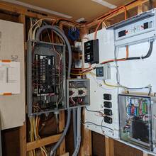


The Panel & Transfer Switches
All the Control mess for the power
2 images
Batteries
Racking up the batteries. The rack is designed for these modules. The rail is slightly too narrow on the bottom to allow the module to slide all the way in. I'll get a grinder and give myself an extra 1/16“ on either side for the screws to slide past.
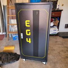


Batteries and Installation
Inverters, Transformers and Batteries
9 images
Battery Docs
Solar PV distribution Panel
This has all been replaced. The units seemed to work but would not handle any kind of a surge once the total load exeeded about 30 amps. I will be updating from here down with new content.

Transformer and Solar Inverter Wall
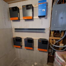


Inverter Wall & Transformer
Inverter wall and sub-panel install
7 images
Inverter Docs
Solar Panels
I'm going with 32 SolarEver 455 Watt mono-crystalline panels. Pics to follow
Project Code
So this is mostly stable pre-alpha quality stuff… Early code used python, which I don't care for so I grabbed the C library for libmodbus, and wrote a small utility and library for the USB/HID relay device. The code also uses a personal “libax” library which has some 'C' functions I've used since before the internet, and I ported some items from my PHP library into it as well. Should contain most everything for some enterprising soul to get something similar working.
C Program to manage this sensor
[keith@powercontrol] /nas-3/work/src/SolarProject<874>panelmonitor --help

Usage: panelmonitor [flags]
  Flags:
  --calibrate     Calibration Request
  --dev|--device {path}
                  Path to RS-485 device
  -d|--daemon     Start a polling loop
  --help          This help text
  --id {n}        No default, pull from sensor {n}
  --interval {n}  Polling interval in seconds
  --once          Poll sensors once
  --reset {arg}
                  now - One time right now
                  daily, weekly, monthly, yearly
  --reset-day {arg}
                  Day of the week/month for energy reset
                  0 = Sun 6 = Sat, or 1-31 day of month
  --set-id {current} {new}
                  Change ID of sensor {current} to {new}
  --show          Show current configuration
  -v|--verbose    Make Noise
I dumped the python cruft, I don't care for python anyway. I needed the ability to do raw read/write to do the energy reset, so I bit the bullet and re-wrote a management application in C. Hack this up as you see fit, it uses libmodbus and a personal C library (libax). Follow the link above for all the code I used in an archive, libraries and all. It also connects to a local postgres instance to log the data.
The old python code is archived here:
Graphana Dashboard
Originally the idea was to use csv, but I decided to do a grafana dashboard to track it from a postgres database. We are polling the sensors every 5 seconds or so. The energy counter in the sensor is an accumulator I will reset it every month for now. The real desire is to track PEAK current draw, to prevent an overload. As panelmonitor runs it can turn off the E/V outlet or flip the pedestal and range back to the main panel based on overall load.
A Screenshot of the dashboard.

The USB/Relay Controller
Danger Will Robinson
The driver on this clunker is stable under linux only if it is the first device enumerated on the bus, ie hidraw0. Any other, and it loses it's mind. I have not really dug into the driver it's part of the kernel source, but it sent me in circles when I had the cables swapped between the USB ports.
Changed gears on this one.
This might work https://www.amazon.com/dp/B07XPFK1ZM?psc=1&ref=ppx_yo2ov_dt_b_product_details
Zer one Control Switch Relay Module, 8-Channel 5V Computer USB Intelligent Control Switch Relay Module Free Driver

I wrote a simple C library to run this thing, and built my own CLI tool. This will probably change as I figure out the device. I need to write an ID parsing routine maybe –on 1,3,5 or –on ALL or –off ALL. For now it's one per argument.
[keith@powercontrol] /nas-3/work/src/SolarProject<875>hidrelay --help

Usage: hidrelay [flags] [device ID]
  CLI to manipulate relays on a USB HID relay control
  [device ID] is the name of the HID device to use
    If only one device present it will use that one
  Default action will show current devices and relay states

  flags:
    -q|--quiet       No Noise
    --on {n}         Turn on relay {n}
    --off {n}        Turn on relay {n}
    --help           This text
    --show           For symmetry (default action)
    --query {n}      Show status for relay {n}
    --rename {old} {new}
                   Rename device from {old} to {new}
                   (5 char limit I think)

--
[keith@powercontrol] /nas-3/work/src/SolarProject<878>hidrelay --off 1 --off 2 --off 3
Relay ID: 6QMBS
  State Change Request:
     1: ON  -> OFF
     2: ON  -> OFF
     3: ON  -> OFF
     4: OFF -> N/C
     5: OFF -> N/C
     6: OFF -> N/C
     7: OFF -> N/C
     8: OFF -> N/C
[keith@powercontrol] /nas-3/work/src/SolarProject<879>hidrelay
Relay ID: 6QMBS
  Current State:
    1: OFF
    2: OFF
    3: OFF
    4: OFF
    5: OFF
    6: OFF
    7: OFF
    8: OFF
